
DVD-quality lessons (including tabs/sheet music) available for immediate viewing on any device.
Take your playing to the next level with the help of a local or online banjo teacher.
Weekly newsletter includes free lessons, favorite member content, banjo news and more.
Premier Sponsors


|
Please note this is an archived topic, so it is locked and unable to be replied to. You may, however, start a new topic and refer to this topic with a link: http://www.banjohangout.org/archive/343500
rudy - Posted - 06/11/2018: 06:08:22
This is the official first day of "National Week Of Making", so I thought it might be appropriate for a "How To" topic.
Complete Guide For Building A Tackhead Banjo
WARNING! This is going to be a LONG AND DETAILED topic, so it might require a lot of intestinal fortitude to hang on to the end, but my intentions are pure and designed to be of service to the forum community.
A few e-mails from folks who were looking for information on "how to make a tackhead banjo" piqued my interest in posting a "How To Build..." topic done in a similar fashion to "Banjo Building 101, a recipe for first time success", but geared toward those folks specifically looking for a tackhead design.
When I gave it some thought I decided that I'd put my own spin on a tackhead design, so this one's going to have a few tricks up its sleeve. It's always a balancing act for me between my inclination to "improve" any particular variety of instrument I'm working on and presenting a "simple" design that's easily made in the average home shop.
Please feel free to jump in anywhere along in this topic if you have either questions or insight about the process. I can present a build using my particular range of skills based on my experience and the tools that are available to me, but really I'd like it to be a sounding board for other possibilities and ideas. To me, that's when a forum works best; when it's used to communicate those ideas that may stimulate someone to think in a different direction. Worried about thread drift? Don't be; I'm actively encouraging it. My posts will serve to bring the topic back around eventually, so jump right in.
Specifications:
12" by 2-3/4" Walnut multi-ply rim composed of 5 layers approximately 1/10th inch in thickness.
Natural hide head retained by glue and tacks
Rim edges rounded over
Rectangular neck mortise houses neck heel extension
Slot at rear for easy adjustment of string height over the neck
Single 5/8" tall low mass bridge
Flat cut walnut neck with heel extension through rim for ease of construction and proper geometry
Scoop at heel end of neck
Standard tapered violin pegs
Synthetic strings
Fretless neck, but details in the plan for adding flush fret markers or actual frets.
The Full-size plan will be posted here in pdf form to download, view, or print as you wish and will include details such as flush marker / fret positions, etc. I'll wait to post the plan until I polish it up a bit.
Since there's a LOT of stuff I want to touch on I'm going to do the posts in a sequence of "steps" where I can add photos and commentary. Since I know how carried away with this stuff I can get, I'll do the photos in groups of 4 (as a single photo). This will keep the sheer number of photos used down to a manageable level. We'll see how that works out... ;-)
It all starts with a road map to get there...
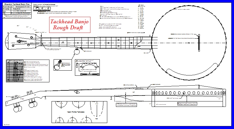
As always, if the photos end up getting unlinked from the text you can go to my home page photos and find them all in the "Tackhead Building Guide" folder. I'll park them there for posterity, but I have no control over what happens to photos and/or links on the BHO server down the road.
July 26th, 2018:
One last edit to load the final pdf plan. The plan is 37" by 20", but it is sized to print as landscape on 8-1/2" by 11" paper. Although that is obviously too small to read there are a couple of ways to utilize the pdf. First, you can enlarge any point in the drawing with your pdf viewer to hone in on details. PDF isn't like a photo, you can zoom in without loosing detail. Second, if you wish a full size drawing you can take the pdf file to a local print shop and they can enlarge it and print it so the borders of the drawing print to the 37" by 20" size. This is an easy job, but be aware that your local chain shop is often staffed by workers who don't know how to operate their machines. When I used to market banjo construction materials I maintained a good working relationship with a professional blueprint shop that did 100 quantity runs for me. Several years back I gave up on the "K" franchise shops because I got tired of having to explain to them how to operate their large format printers. YMMV locally.
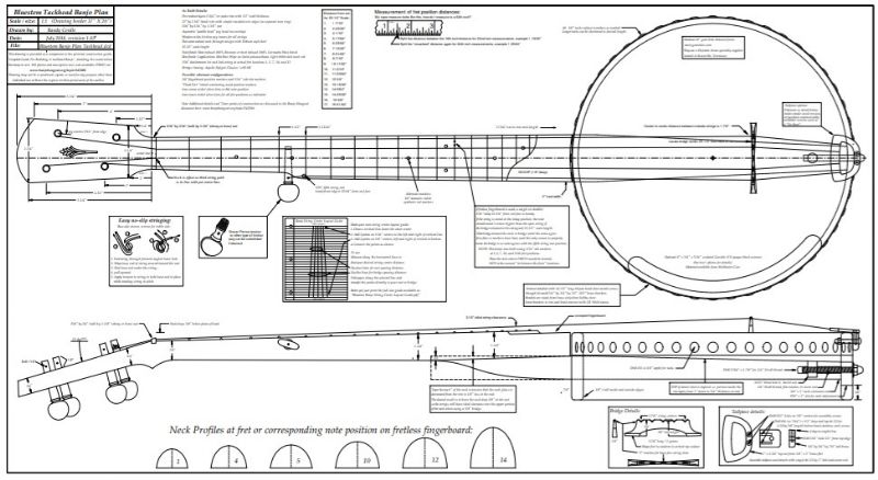
View, use, download, or save the PDF below:
Edited by - rudy on 08/13/2018 20:00:09
rickhayes - Posted - 06/11/2018: 07:38:14
I'm working on my first mountain banjo based on information you have previously shared. I don't really have the most appropriate set of tools but I'm improvising as best I can and it's getting there. I'm looking forward to this build too, Rudy. Thanks.
rudy - Posted - 06/12/2018: 05:54:56
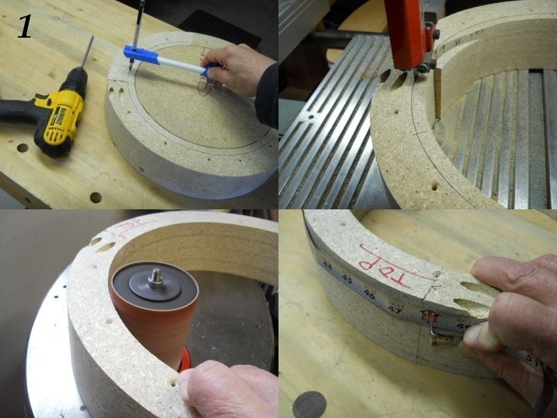
1. I modified one of my 11" forms to create a form to make a 12" rim. I band sawed through the form and added pocket screws across the cut. I then inserted a 11" disc of particle board and marked the center for the beam compass point so the 12" rim diameter could be drawn on the form.
2. The band saw was used to cut the form to the new 12" diameter.
3. The inner surface of the 12" form was sanded with the vertical oscillating spindle sander using a 80 grit 3" sanding sleeve.
4. The outside circumference of the form was approximately 48"; a good length to make the rim laminations.
rudy - Posted - 06/13/2018: 05:49:09
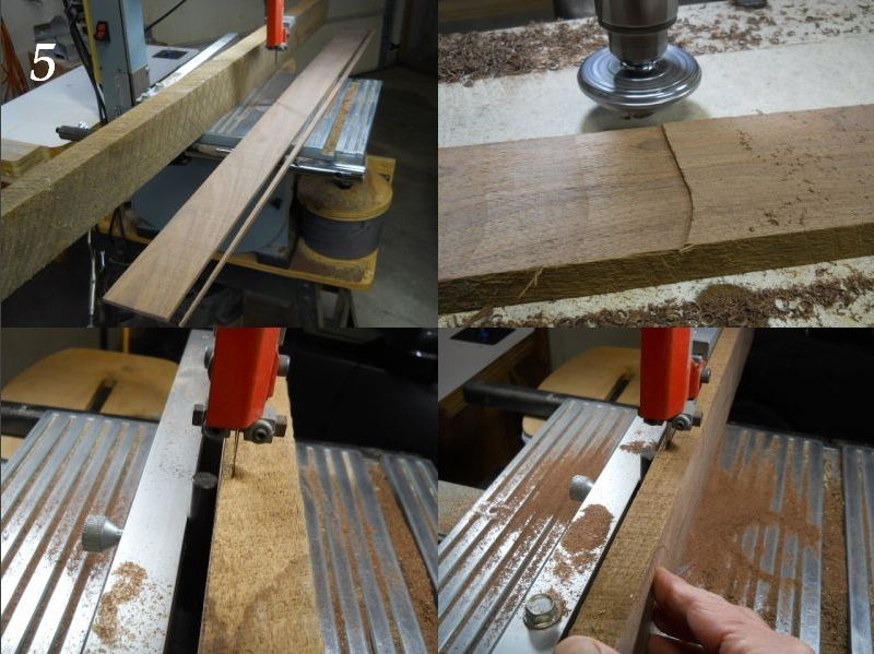
5. Walnut rescued from an OLD barn that was torn down was used to make this banjo. Here it is being used to make the rim laminations. There's quite a differance between the original rough sawn lumber, as seen against the band saw fence, and the beautiful color and grain exposed after cutting and planing. I'm using a Delta 12" band saw that I added a 3" riser to so I can re-saw up to 9", which I do for octave mandolin and guitar tops and backs occasionally. The band saw is fitted with a 1/2" 3 TPI skip tooth hard back blade that I use for all purposes, including cutting brass and aluminum with.
6. After each layer is sliced off using the band saw the freshly sawn surface is planed to make a fresh face to use against the band saw fence.
7. Re-sawing is done by using the single point guide pin, shown attached to the fence. This is necessary to counter the blade following its preferred "lead angle". Plenty of details on re-sawing if you do a quick Google search.
8. The single point guide permits the board to be angled so the blade will follow the correct path and not drift off to one side or the other.
Photos 5, 6, 7, & 8:
Edited by - rudy on 06/13/2018 05:50:43
FlyinEagle - Posted - 06/13/2018: 07:07:30
Thanks for taking the time to do this Rudy.
I have been tooling up my shop to give the 101 banjo a go. I might end up doing this instead if I think the lamination bending and rim construction is realistic with what I have available. I snagged a 30 year old 14” benchtop Delta clone off of CL for 50 bucks a few weeks back. Not bad quality for an Asian knock-off (Tradesman).
rudy - Posted - 06/13/2018: 08:01:19
quote:
Originally posted by FlyinEagleThanks for taking the time to do this Rudy.
I have been tooling up my shop to give the 101 banjo a go. I might end up doing this instead if I think the lamination bending and rim construction is realistic with what I have available. I snagged a 30 year old 14” benchtop Delta clone off of CL for 50 bucks a few weeks back. Not bad quality for an Asian knock-off (Tradesman).
Hi Jeff, you're entirely welcome and thanks for checking out the topic.
There's enough diversity within types of banjos that I believe many folks simply bypass a topic relating to a "tackhead" design, even though there would be many areas that might prove useful to other types of banjos.
This particular tackhead is going to have some of my favorite open back building techniques thrown in, so it ends up being more than a "stretched skin over a grain measure" design.
I would encourage you to keep moving forward in your banjo building skills, and the best way to do that is start simple and move up the food chain as you get some time and actual hands-on experience. Tool-wise, it's often the case that you can simplify steps to meet what you have available. I've been doing this for something on the order of 30 yeas, so I've slowly permutated my shop and tooling to match the designs I've come up with, so I can work easily and fairly quickly with a minimum of sweat equity. I'm all about easy... 
FlyinEagle - Posted - 06/13/2018: 09:03:11
Hi Jeff, you're entirely welcome and thanks for checking out the topic.
There's enough diversity within types of banjos that I believe many folks simply bypass a topic relating to a "tackhead" design, even though there would be many areas that might prove useful to other types of banjos.
This particular tackhead is going to have some of my favorite open back building techniques thrown in, so it ends up being more than a "stretched skin over a grain measure" design.
I would encourage you to keep moving forward in your banjo building skills, and the best way to do that is start simple and move up the food chain as you get some time and actual hands-on experience. Tool-wise, it's often the case that you can simplify steps to meet what you have available. I've been doing this for something on the order of 30 yeas, so I've slowly permutated my shop and tooling to match the designs I've come up with, so I can work easily and fairly quickly with a minimum of sweat equity. I'm all about easy...
Thanks Rudy.
Yes, I definitely will be looking for ways to use what tools I have. My grandfather taught me my basic woodworking skills starting when I was old enough to swing a hammer, and the only power tool he ever owned was a drill, so I have been working with hand tools and improvising my whole life.
I am adding tools that will serve me in my other projects as a priority, and adding on other items as I go (like tossing another c clamp in the cart when I am at the hardware store for other stuff). I will probably try to find a used benchtop drill press in the near future. I have limited space for all of this at our current home, so all of my shop tools must be stored and taken out when I need them. You figure out how to group like-tasks very quickly with my current setup, haha.
Starting simple is indeed my plan. I have been incorporating elements that I think will be useful for banjo building into other projects I am working on. If I don’t think the rim laminations for this tackhead will work out for me, then I will just order the hand drum you recommend in the 101 guide. I really like the idea of making the rim myself though, so we’ll see how it goes.
I’m not in much of a hurry either way. I have a lot to learn, so I can’t be in a hurry.
rudy - Posted - 06/14/2018: 05:49:27
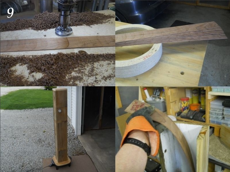
9. Layers are final thickness planed to 7/64", approximately .010". The rotary planer does an excellent job of this and it's easy to set up by using a 7/64" drill bit as a "gauge" to set the gap between the cutters and the table.
10. Five layers will be used to create a 1/2" thick rim wall, but the rough lumber made 7 layers. I check the lamination right before throwing it in the steamer and run it over the belt sander to knock down any proud edges left from the planing operation.
Now would be a good time to read through the "Goldilocks lamination" topic" that I posted a while back if you are unfamiliar with steam bending. My technique makes it fairly easy to end up with a successful first foray into steam bending.
banjohangout.org/archive/330189
11. Each layer is steamed for 15 minutes, I prefer to work in a leisurely manner, taking my time when steam bending.
12. Ready to bend after 15 minutes; layer can easily be flexed to the desired curvature.
mutantmoose - Posted - 06/14/2018: 08:02:48
I won't comment every time, but THANKS for posting this - looks great! I'm also glad to see that someone else proudly wears cheap digital watches still. :D
rudy - Posted - 06/14/2018: 15:03:38
quote:
Originally posted by mutantmooseI won't comment every time, but THANKS for posting this - looks great! I'm also glad to see that someone else proudly wears cheap digital watches still. :D
Casio F-91W for as long as I can remember. My Grandkids have now started wearing what ever watch Grandpa wears... smart kids.
My sweet wife wanted very badly to purchase me a Tag-Hauer for my 50th birthday and really had trouble understanding a guy that was hog-heaven happy with a $10 watch. I had to explain to her that there's a great mystery that even I do not fully understand, but analog watches WILL NOT function more than a few weeks for me. It must be my magnetic personality...
Then again, I'm REALLY frugal and the idea of $1000+ spent on a watch is NOT my idea of generating good Karma.
mutantmoose - Posted - 06/14/2018: 19:02:36
quote:
Originally posted by rudy\Then again, I'm REALLY frugal and the idea of $1000+ spent on a watch is NOT my idea of generating good Karma.
I get it - I teach kindergarten, and the last thing I want to wear is something expensive. I'm just going to get tempura paint all over it anyways. You should see my cell phone holster!
rudy - Posted - 06/15/2018: 05:31:05
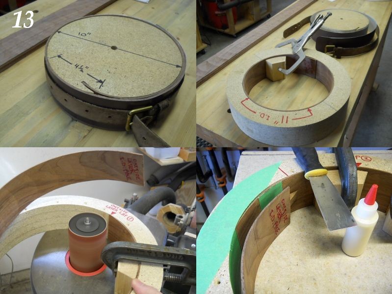
13. Layers are wrapped on the bending form and allowed to cool slightly as the next layer steams. An old belt is used to cinch up the lamination until it cools and sets a bit. The bending form is made so the start of the layer can be tucked in the slot to hold the end and quickly rolled up. Speed is of the essence, as this has to be done while the thin layer is still soft and pliable. The entire process is covered extensively in the previous link to the archived "Goldilocks Rim Laminations" topic.
14. After cooling slightly the layer is placed in a spare form and clamped as it continues to dry out. An overnight stay in the layer hotel is a good thing to shoot for.
15. The layer is slipped into the 12" form and clamped so tapered edge can be sanded with the vertical oscillating drum sander. Sanding the overlap in this manner will create the best possible lapped joint for the outer layer of the rim. This outermost layer is done in this slightly different manner than the other layers because the lap joint needs to be attractive when viewed as a finished rim.
16. Areas are masked where glue might not be wanted. Notice the inside of the form is covered with a single layer of tape before the first (outer) layer is glued up. Overlap has glue applied and is clamped using a cork padded caul. The portion of the layer with red marker is extra overlap length and will be removed in the following steps. It will end up over the green masking tape placed at the edge of where the finished lap will end.
Photos 13, 14, 15, & 16:
Edited by - rudy on 06/15/2018 05:33:44
rudy - Posted - 06/16/2018: 05:02:59
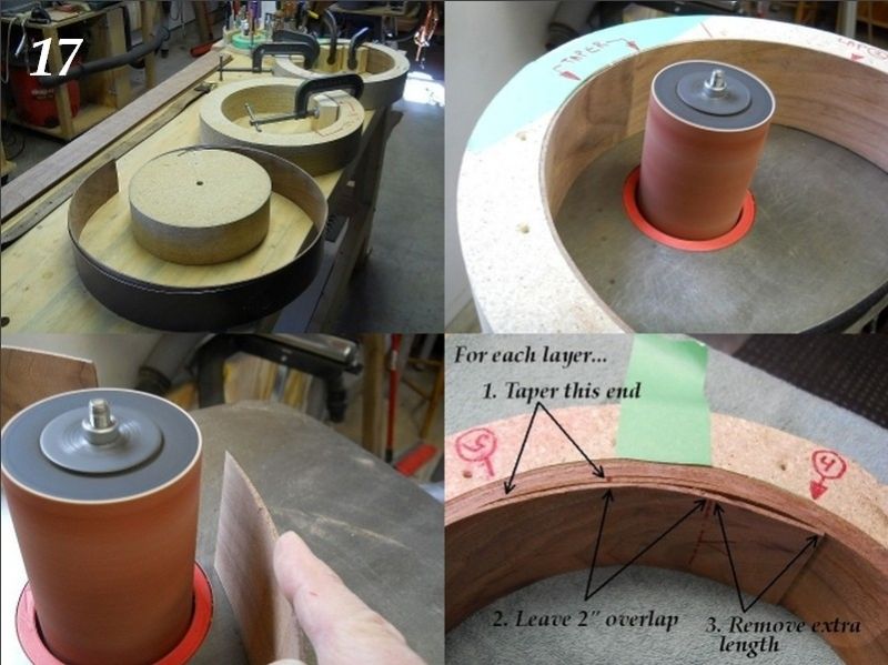
17. Assembly line... (rear) outer lamination that was just clamped is left to dry, (middle) spare form awaiting new layer, (front) freshly bent lamination "un-belted" and ready to move to the middle form so it can dry completely before use. The best way to do this is to have an area off to the side where all the intermediate steps of the rim making process can be parked for a while. I have a seperate roll around table that I use, but I threw it all on the workbench for a "beauty shot".
18. The outer layer has the tapered tail sanded to complete this first layer which will become the base upon which the subsequent layers are added.
19. The "starting end" of the second lamination is sanded to form a ramp that the end will nestle against.
20. Here's a view of all the inner layers. Do remember to stagger the lap joints for strength and to end up with the final lap where you want it to be. I like to position the final lap where it is least visable from the playing position. I also position laps away from the neck and end mortise areas. The "start" taper is sanded (as per previous photo...), the layer is positioned and marked, and trimmed, leaving a 2" overlap past the tapered starting section. A band of masking tape will be placed just beyond the end of the "starting area" taper to facilitate removing the excess length. We'll see that reviewed in the next set of photos.
Photos 17, 18, 19, & 20:
Edited by - rudy on 06/16/2018 05:18:07
rudy - Posted - 06/17/2018: 05:02:57
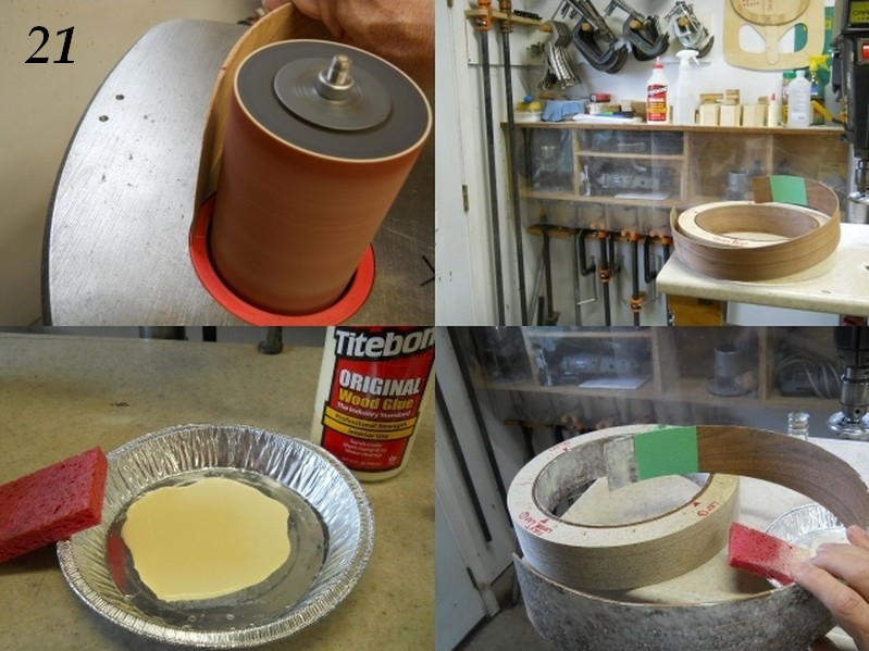
21. Another shot of the "starting area" of the rim layer being sanded with the vertical oscillating spindle sander. I can't say how useful this sander is for many purposes. I purchased mine on a whim, thinking "Will I actually ever use this thing?"
22. The layer has been prepared and is ready to apply glue and add to the previous layer.
23. To apply glue with uniform coverage and a minimal amount of excess to clean up I often use a puddle of fresh Original Titebond and a dampened sponge. You can quickly develop a feel for doing this so you dispense the correct amount of glue and have little excess to clean up.
24. Surfaces have been "patted" with the glue sponge and placed into the assembly form against the previous layer. It's good to do this fairly quickly; obviously we have all the clamps and cauls close at hand and ready to use...
Dan Drabek - Posted - 06/17/2018: 09:14:01
It's always fascinating to see how others work. Rudy's techniques are always inventive, clever and they do the job.
I know from personal experience how much time and work is involved in documenting a build and the effort is appreciated. I always learn something from Rudy's examples.
DD
rudy - Posted - 06/17/2018: 09:43:28
quote:
Originally posted by Dan DrabekIt's always fascinating to see how others work. Rudy's techniques are always inventive, clever and they do the job.
I know from personal experience how much time and work is involved in documenting a build and the effort is appreciated. I always learn something from Rudy's examples.
DD
Thanks, Dan.
There doesn't seem to be a whole lot of interest in actual "building" lately on BHO so I thought I'd do this one for fun.
geemott - Posted - 06/18/2018: 04:32:32
Do you have to re-shape the cauls after every layer, to get a good solid clamp?
FlyinEagle - Posted - 06/18/2018: 05:34:20
Rudy, you commented on the drum sander, which I was going to ask about.
You used it in a lot of steps so far, how did you handle those steps before you had the drum sander? Drum in a drill press?
rudy - Posted - 06/18/2018: 05:41:58
quote:
Originally posted by geemottDo you have to re-shape the cauls after every layer, to get a good solid clamp?
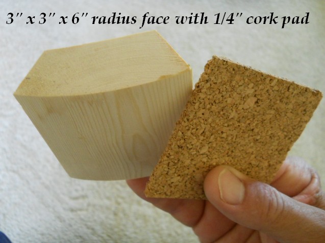
Garry, Excellent question. The cauls are cut 3" by 3" with a 6" radius face and the cork pads are a matching size and 1/4" thick. In use the cork compresses enough to conform to the change in diameter of the rim as layers are added. Ideally you would use a caul perfectly matched to the diameter, but it works fine to use a single radius.
rudy - Posted - 06/18/2018: 05:51:58
quote:
Originally posted by FlyinEagleRudy, you commented on the drum sander, which I was going to ask about.
You used it in a lot of steps so far, how did you handle those steps before you had the drum sander? Drum in a drill press?
Hi Jeff.
I've used a lot of adaptive techniques over the years based on tools I've had at the time. Yes, I have used a drill press with a sanding drum in the past.
For forms I've also worked carefully to cut as close as possible with the band saw and trued up the faces with a hand drill fitted with a 2" diameter 80 grit sanding drum. I find that to be useful for so many things that I keep a drill set up with that permanently so I can use it without even having to pull the drum out and chuck it up. No great expense, as I purchased the drill several years ago when walking through Menard's and finding them on clearance for $5. I'll be using that drill later on at some point so you can get a peak then.
rudy - Posted - 06/18/2018: 05:57:20
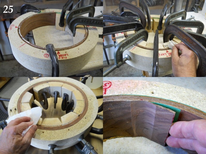
25. Adding clamping cauls. It's important to make sure the layer is positioned all the way down; you can see a clamp used to make sure the layer stays down as the cauls and clamps are added. The cauls are cut from 3" lengths of common 2X4 and have the faces band sawed / sanded to conform to the inner face of the rim form. I keep a stack of 1/4" cork pads cut to match the caul face size (3" by 3") to add between the caul face and the layer surface to evenly distribute clamping force. It's also important to add the cauls and clamps sequentially, otherwise gaps will be created in your rim.
26. All cauls in place and excess glue is removed.
27. Cleaning up glue squeeze out with a small piece of moistened paper towel.
28. After each layer dries sufficiently the cauls are removed and the inner layer has the excess length removed and the inner face is trued up if more layers are to be added. The overlap is removed by sanding with the vertical oscillating spindle sander and the masking tape underneath is removed.
rudy - Posted - 06/19/2018: 05:21:30
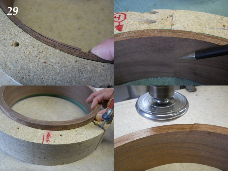
29. The inner profile of the layer is marked on the excess length of the layer and it is sanded to produce a perfect layer diameter.
30. The pencil is pointing to the actual edge of the overlap. It doesn't get much better than this for a layer-built rim.
31. When it's time to remove the rim from the form the screws holding the form together are removed, the form slightly opened by wedging a screwdriver into the joining area, and the rim is then removed.
32. I use a Safe-T-Planer to true the edges of the rim and reduce it's overall height in 1/16" passes until it's at the desired 2-3/4" height dimension.
Safe-T-Planer in use example on a previous project:
Edited by - rudy on 06/19/2018 05:30:01
rudy - Posted - 06/20/2018: 05:00:30
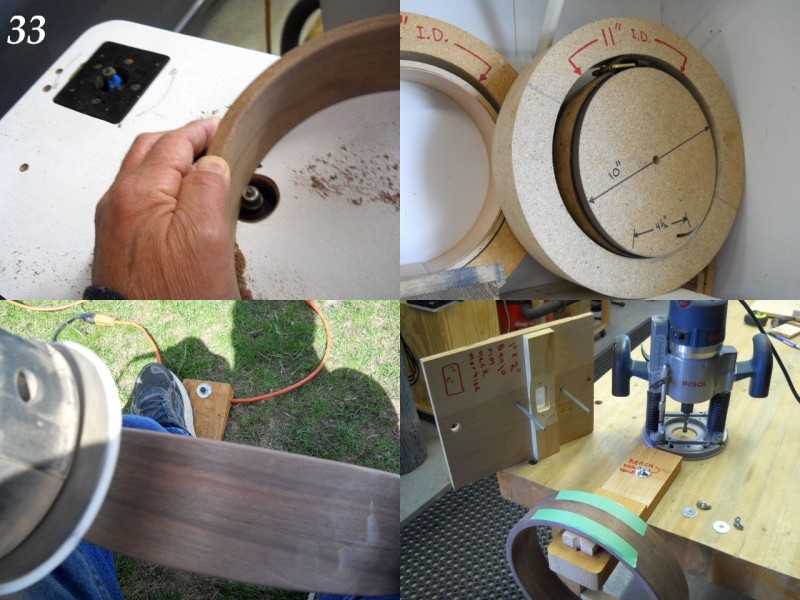
33. All four edges are rounded over using a bearing-piloted 1/8" carbide round over bit using a table mounted router.
34. A photo showing forms and rim parts nested together and set aside on a shelf. (They don't ALWAYS have to monopolize the workbench...)
35. The rim surface gets sanded with a 220 disk on the 5" random orbit sander. The momentary foot switch allows me to "pulse" the sander and makes fine control of the sanding operation a breeze. I use Indasa 5" 8 hole hook and loop discs which cost about 25 cents each when purchased in bulk. I get a couple hundred at a time, and it's the ONLY grit that I keep in my shop. The 220 works for everything and I don't have to keep multiple grits on hand. Incidentally, the Indasa discs are miles better than anything I've used in the past and they last a LONG time between disc swaps. I get them from Lehigh Valley Abrasives.
36. The rim is placed on a cradle to form the 1" by 2" neck extension mortise. I use a 3/8" diameter solid carbide up cut spiral bit in a plunge router. It's easy to figure this out be looking closely at a few of the photos. I do ALL my open backs with this method for reasons that will become clear as we go on. In case you're wondering, the rim is still very strong after the mortise is routed due to the way the rim is made. You might be able to break it if you drove a truck over it, but why would you do a thing like that?
rudy - Posted - 06/21/2018: 05:46:53
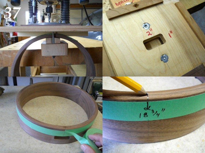
37. A side view of the plunge router being used to create a perfect 1" by 2" rim mortise. The rim is sandwiched between the routing jig and a scrap of sacrificial backing material under the rim. The top jig, rim, sacrificial backing, and mounting base are all fastened together with two short pieces of 1/4" by 20 all thread rod. The mortise is clean with no chance of tear out on the front or rear surface of the rim.
38. Top view of the mortise jig, showing the rim mortise after it has been routed. The outer guide rails on the jig are positioned so the 3/8" router bit creates a perfectly sized 2" by 1" mortise.
39. A strip of painter's tape is wrapped around the rim and trimmed to exact length.
40. The tape is removed, marked at the exact center length and re-wrapped in the same position on the rim. This precisely locates the tail piece center, as well as locating the center for the end of the neck extension.
Edited by - rudy on 06/21/2018 05:49:27
FlyinEagle - Posted - 06/21/2018: 06:10:37
These are the cash money tips right here.
That router jig and the tape tip are keepers, for sure.
Dan Drabek - Posted - 06/21/2018: 10:49:17
I also like the tape trick for finding the opposing centers. Perfectly accurate and saves a lot of drafting time.
DD
rudy - Posted - 06/22/2018: 05:34:31
Thanks Jeff & Dan.
I'm throwing in some of my favorite building techniques as I go. I can't cover everything I've worked out over the years, but the things that pertain to this particular tack head build are included.
rudy - Posted - 06/22/2018: 05:42:22
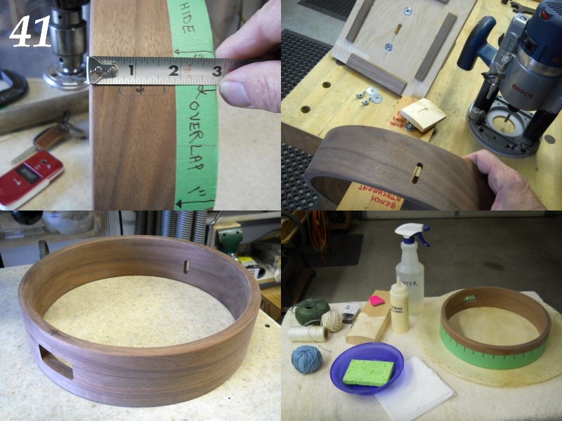
41. Layout for the 9/32" x 1" slot, centered 1-1/8" up from the bottom of the rim. The 1" tape was placed back on the top of the rim to show the relationship of the hide overlap to the adjustment slot. For those unfamiliar with what is being "adjusted", the slot allows the neck extension to be raised or lowered to alter the neck's rake angle, thereby changing the string height over the neck. A single 1/4"-20 acorn nut locks the neck extension in place. I love the option of being able to adjust neck rake angle in less than 60 seconds without the need to even slack the strings!
42. The slot is made in an identical manner as what was done to make the neck mortise. Here you can see the rim slot immediately after it is cut and the rim removed from the slot forming jig. The consumable backing block is laying on the jig base directly behind the rim. The area where the router bit cut into the rounded backing block can be seen in the photo.
43. Neck mortise and end slot have been completed and rim is now ready for attaching the hide. Truly a point of celebration!
44. Everything here is pretty self-explanatory. Notice the lower side of the rim has been wrapped with a 2" wide layer of painter's masking tape pre-marked with 1" divisions. I may use these as a guide to installing tacks, so it's easy to mark the divisions out before the tape is added to the rim. I grabbed a bunch of various twines and string to use in the process of attaching the hide. Notice also that the hide was drilled around the outside edge at 1" intervals before it is soaked. The water-dampened sponge in the bowl will be used for smoothing out the glue application on the rim if necessary.
The rounded board gets clamped on the bench when the tacks are installed, but tacks are gonna happen a bit later.
Edited by - rudy on 06/22/2018 05:47:15
rudy - Posted - 06/23/2018: 06:12:56
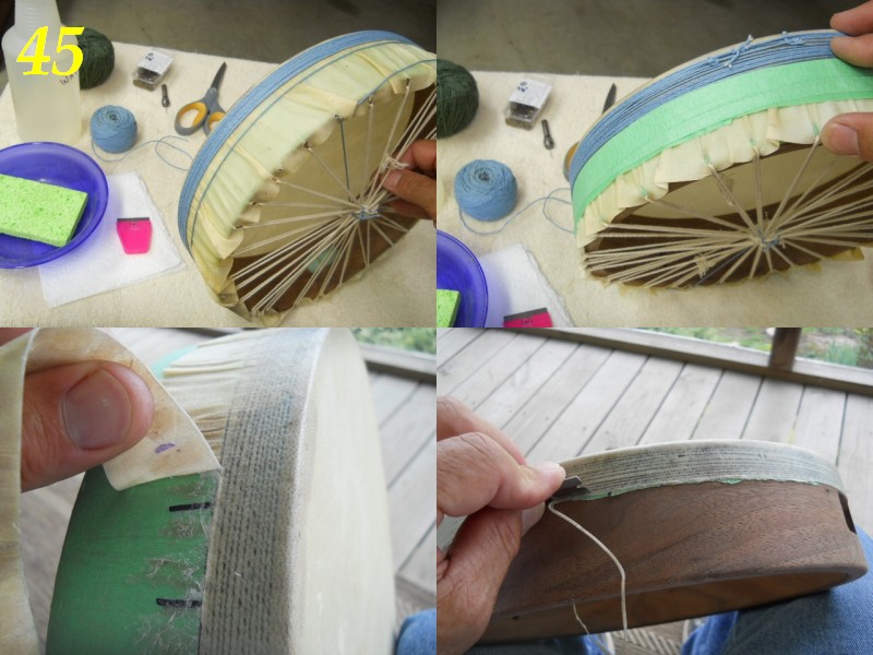
45. The medium thickness goat hide (18" diameter) was soaked in warm water (bathtub...) for 1/2 an hour and the excess water patted off with a cotton towel. A generous coating of Original Titebond was applied to the top edge and down over the side of rim. Working expediently, the hide is pulled evenly over the rim and stitched between the holes, working from side to side. The hide is pulled just snug, to ensure it will be sufficiently tight when dry. This also helps smooth out the wrinkles on the portion of the hide extending over the sides of the rim.
As soon as all those holes are laced up it's time to wrap string tightly over the hide, starting at the top of the head and progressing downward. The remaining wrinkles can be pushed down and smoothed out as the wrap progresses. The idea is to get the hide smoothed out down to where the wide masking tape starts.
46. As a final step the area below the 1" overlap is tightly wrapped with masking tape. This is just a bit of extra insurance towards getting the skin to lay flat against the rim.
47. Set the rim aside for a couple days... no sense getting impatient now. Remove all that string and use scissors to trim away some of the wrinkly excess hide that was used to cinch it up for the drying process. Next step is to cut down through the hide carefully with a single edged razor blade where the hide meets the wide masking tape. You can safely dab a small amount of water on the excess hide overlap to soften it if necessary. Carefully peel it away, re-cutting along the line as needed to make sure you don't pull up the part of the hide that needs to remain attached. This all sounds difficult... it isn't.
48. I carefully re-trimmed a few of the less perfect areas and peeled off the excess ragged edge of the hide. The string I used was blue, and you can see a bit of dark imprint on the hide where the string was wound; I actually like the look.
Edited by - rudy on 06/23/2018 06:17:55
mutantmoose - Posted - 06/23/2018: 07:18:03
That is NOT how I figured it was done. Holy cow. I was expecting a lot of tacks at this point.
rudy - Posted - 06/23/2018: 08:02:24
quote:
Originally posted by mutantmooseThat is NOT how I figured it was done. Holy cow. I was expecting a lot of tacks at this point.
I always premise my builds with the idea that I often veer from conventional technique, usually based on my way of improving some aspect of the build.
I have to admit I've played with stretched hide many years back and knew I wanted to do something different, as the wrinkle problem gets swept under the rug in most of the "Tackhead" builds that I've seen discussed in the past. My M.O. from the inception of this build was to eliminate a few of the issues I knew would be a problem, at least for me.
I'd be interested if anyone else who does tackheads has dealt with the wrinkle issue differently, but I can confidently say this method ended up being highly pleasing, both from mechanical integrity of the edge and the total absence of wrinkles. As a matter of fact, I'd say that the actual tacks add very little in strength, but do add to the attractiveness of the completed banjo. Plus, if I didn't add the tacks I couldn't call it a "tackhead"!
Most of the tacked heads you see have been done on gourd banjos where the hide doesn't have near the wrinkle propensity as when you turn the edge down 90 degrees as done using a straight sided rim.
rudy - Posted - 06/24/2018: 05:48:12
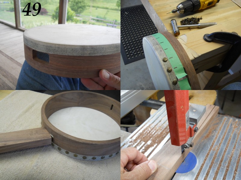
49. All in all, a fine looking "tackhead", even before tacks!
50. A wrap of tape pre-marked with 1" intervals is wrapped around the rim as a guide for positioning the tacks evenly. I pre-drilled the tack locations with a #55 drill bit to a depth of 3/8". The bit is marked for the correct depth, as you don't want to drill through the rim! The tacks were decorative head upholstery tacks with a antiqued brass finish from the fabric store. They were 7/16" long and I trimmed them off and re-pointed them, as I just wasn't comfortable coming that close to going through the rim.
51. The neck extension that will pass through the rim mortise is cut to exact size for the mortise. Here the thickness is being verified; you want a close fit that will just slide through the mortise after the edges are rounded over. The details for all of the parts will be listed on the final construction print PDF.
52. After the neck extension is sized for the mortise the portion that runs through the inside of rim is tapered down to 1" width at the tail. The top portion is also tapered down to 3/4" thickness at the tail. The two REAR edges can be sanded smooth and rounded over the entire length with a bearing-piloted 3/16" round over bit, but the TOP edge that will mate to the actual neck is rounded only as far as the outer edge of the rim. The remaining length needs to be flat, as it will be angled and glued to the neck as per the construction drawing. This will be shown in up-coming photos.
Stephen45710 - Posted - 06/24/2018: 19:32:14
This is awesome. Thanks for your continued enthusiasm and willingness to share your knowledge. There are already lots of banjos that exist because of your tutorials, now there will be even more!
rudy - Posted - 06/25/2018: 05:56:46
quote:
Originally posted by Stephen45710This is awesome. Thanks for your continued enthusiasm and willingness to share your knowledge. There are already lots of banjos that exist because of your tutorials, now there will be even more!
Thanks, Stephen.
Everyone might not be interested in a tackhead, but the point is really about the process of working out methods of construction that might be different than what we normally consider. If this topic gets someone's creative juices flowing or demonstrates a technique that might be adapted to their needs then it's accomplished the intended goal.
rudy - Posted - 06/25/2018: 06:04:31
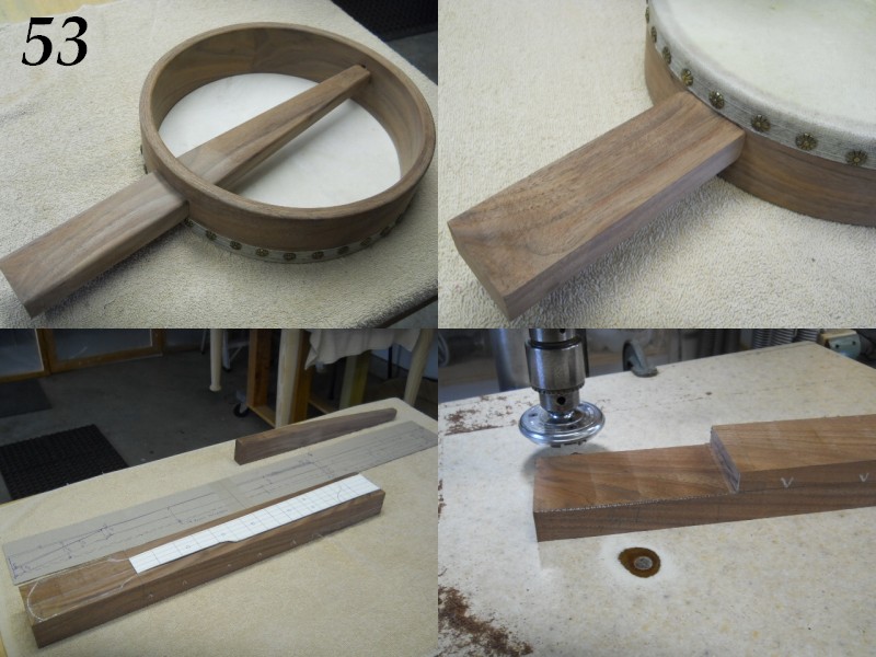
53. Here's a shot of that neck extension that will serve as the "platform" on which the neck will be glued to. The extension tapers both in width and height down to the end point where it anchors to the rim. The tapers start 1/2" from the inside wall of the rim. This reduces a bit of weight, eliminates excess bulk, and just looks nice.
54. Here you can see the top of the neck extension where the neck will be glued. The top surface of this part of the neck extension will also be angled down a bit to form the back (rake) angle for the neck. Hang on, we'll get there...
55. Enough of that rim and neck extension stuff! Let's get to the important part. Here you can see the shape of the neck has been transferred to the neck blank proper, a 3" by 1-3/4" by 24" piece of the re-claimed barn walnut. All the details are taken from the plan and transferred directly to the wood. The finger board portion is transferred to the blank, mating the actual center of the neck heel, center of the nut, and center of the top of the peghead to the center line of the blank.
(You don't need to think much about this right now, but the neck will be skewed a bit when it's glued to the neck extension so the third string path will end up directly in line with the rim center line. You'll get the lowdown later, but this will ensure that the strings will be centered over the neck at the heel.)
56. The BOTTOM of the neck heel area is notched with the band saw and then planed to create a perfectly flat and true gluing surface for the neck. The amount removed will dictate where the top edge of the "scoop" will be in relation to the plane of the head; I'm making the scoop surface flush with the head on this build.
Again, the Safe-T-Planer excels at this kind of stuff, although there's certainly all sorts of other ways to create a gluing surface. I've just been using the STP so long it ends up being my go-to tool for many tasks.
rudy - Posted - 06/25/2018: 20:30:06
quote:
Originally posted by rubicona great thread Rudy!
Thanks. By my reckoning we're just over the half way point. Hopefully there will be something in it for most everyone, even if for entertainment value only.
rudy - Posted - 06/26/2018: 09:16:03
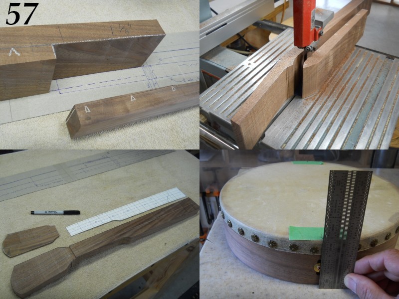
57. The top portion of photo #57 shows the main neck blank with its gluing surface prepared. The top surface of the blank will also become the surface of the finger board; the 1-1/8" thickness (as indicated in the photo) will later be reduced to 1" when the scoop is formed. This will position the scoop surface flush with the surface of the head.
The bottom portion indicates the wedge shape taper that will be produced by planing that area of the neck extension. That slight downward angle will pitch the neck back slightly, setting the appropriate geometry to end up with correct action over the upper portion of the fingerboard when the strings are elevated by a 5/8" bridge at the correct distance across the head.
58. The side profile of the neck was drawn on the blank previously (photo #55) and those side profiles are now cut out with the band saw. The saw cuts are kept close to the line, but care is taken to NOT cut past the lines since they establish all the correct proportions of the neck. Use extra care on the top surface cut, as it will be used as the visible face, hopefully requiring minimal sanding to clean up the cut and make it look good.
59. With the side profile cut, the top surface can be carefully cut to the drawn top profile. The fingerboard pattern is shown next to the neck, although we're making this banjo a "traditional" fretless. Frets and position markers can be added if desired and those details are included on the plan.
If you look closely you can see a full size side profile drawing in the background. Since this is a new design carefully work out all the angles before any shaping, as we really don't want any of those "OOPS!" moments down the road. The old "Ounce of prevention is worth a pound of cure" thing...
60. I've added a small screw and washer in the end of the neck extension in preparation for verifying the angle that will be formed on it's top surface... where the actual neck will be glued. Notice the short lengths of painter's masking tape that have the centers of the end slot and neck mortise transferred to them. These will be used to establish the actual neck mounting "skew" angle. That slight angle will ensure the true centerline of the rim will be congruent with the third string path. This will ensure the strings will center over the neck heel and not run off to one side or the other.
Enough for now, we've covered a lot of important points and I'll work to clarify anything that might be a bit hazy in later posts.
rubicon - Posted - 06/26/2018: 20:12:32
I am curious why the scoop will be placed so you lose the 17th fret ?
rudy - Posted - 06/27/2018: 04:53:44
quote:
Originally posted by rubiconI am curious why the scoop will be placed so you lose the 17th fret ?
In the drawing you can see a partial 17th fret across the double ogee scoop.
It's common to see the "partial 17th" as it ends up giving you the best of both worlds; the few notes that are very occasionally used on the first and second strings while extending the scoop on the thumb side, where it matters most.
The need for frets beyond the 17th is obviously a choice based on playing style, but for clawhammer players it's almost always no man's land.
Fret positions are shown on the drawing in case someone wants to utilize frets, but this tackhead is going to be made as a fretless banjo.
rudy - Posted - 06/27/2018: 05:12:24
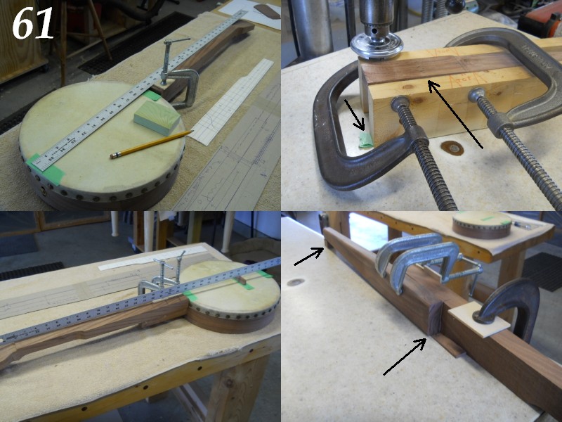
61. The neck is temporarily attached with a small C clamp with the heel centered over the neck extension and the neck "skew" angle set so the third string position at the nut lies directly in line with the centerline of the rim. (The "centerline of the rim" is the line that connects the center of the end slot and the neck mortise.)The aluminum rule straightedge verifies this. The end of the neck heel is now marked with a radius that will match up to the rim. The neck is removed and the neck heel cut and sanded with the 3" sanding drum on the vertical oscillating spindle sander so it will mate attractively to the rim. A small gap will remain to clear the tack heads, but it will look fine. The face of the heel radius can be angled at about 2 degrees or left at 90 degrees. An angled face can be brought closer to the rim, but either way is fine.
62. I chose to refine the peghead top surface a bit by surfacing it with the Safe-T-Planer. I start off with shallow cuts and take LIGHT passes until the planed surface intersects exactly where the rear face of the nut will be located. When the side profile of the neck blank was cut, the peghead surface was cut to be slightly below the fingerboard surface. The nut will be recessed a bit more and will butt against the "fingerboard end". This will be more easily understood from later photos.
Notice the planer cut line for this first cut on the peghead surface. Since I'm using the set of "outriggers" to hold the neck, this line can be corrected for angle by adding layers of masking tape under the appropriate side. Here there are 8 layers added so the line that will intersect the nut edge location will be 90 degrees to the neck blank and not angled to one side or the other.
63. I removed the neck extension and used the exact same planer setup to taper the top of the extension downward from the rim to create the back (rake) angle for the neck. The neck extension is again temporarily attached to the rim and the neck is clamped with 2 small C clamps so the third string path is congruent with the rim centerline. I'm using a 48" aluminum rule to check the string height using a 5/8" temporary bridge. I'm happy with how everything looks here.
64. The neck and extension are removed WITHOUT moving the clamps and the neck is positioned on its side on a flat non-stick table and clamped down lightly in a way that doesn't disturb the angular alignment. Small shims and/or wedges are added at the ends of the neck and extension so neck and extension can be removed, covered with Original Titebond, and returned to their exact positions to be clamped for gluing.
rudy - Posted - 06/30/2018: 18:53:40
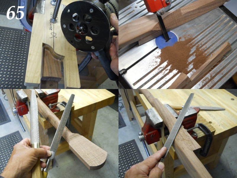
65. Routing the scoop. This shouldn't take a lot of explanation, but the pattern board is clamped on the neck surface and holds the router at a consistent depth while the bearing guided 3/8" carbide cove bit is used to create the double ogee scoop. It's quick and simple once you understand the setup and make a router jig to match your desired scoop profile.
66. Trimming away excess at each side of neck. I normally use a different profile, cutting away waste in two separate angles. This tackhead neck profile I decided to do as more of a shallow vee just to shake up my normal neck profile and see if I liked the vee shape as well as my standard "C" neck profile. It starts with 30 degree cuts extending to about 1/4" from the fingerboard edge and then progresses to rasp work. (Normally there would be an attached fretboard, but this tackhead has an integral neck / fretboard.)
If you prefer a more rounded "C" shaped neck you can follow the "Bluestem Neck Shaping Guide" PDF included as suplementary material at the bottom of this post.
67. I'm using two rasps, a courser "Sculpture House" rasp ($20 from Dick Blick Art Supplies) and a finer cut #50 Nicholson (normally around $50, but came free of charge from Highland Woodworking as a thank you for featuring my shop in their "Show Us Your Shop" section of their free on-line magazine. Jason Romero did a photo journal of his 200th build and stated that the Nicholson #50 was the only rasp he used for neck shaping, so I guess that's pretty high praise.
68. Shaping the heel area with the Nicholson #50 rasp. Not much to pontificate about here... stay tuned.
"Bluestem Neck Shaping Guide" PDF below:
rubicon - Posted - 07/01/2018: 08:14:08
This is awesome !!! Love the v profile !
Edited by - rubicon on 07/01/2018 08:16:10
rudy - Posted - 07/03/2018: 05:07:32
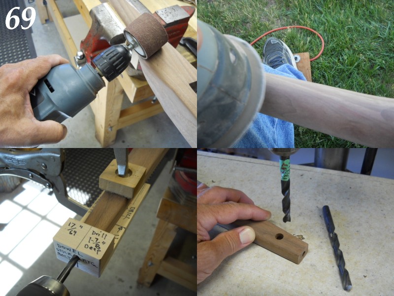
69. I keep a drill permanently set up with an 80 grit 2" sanding drum for all those little shaping tasks that fall between basic rasp work and finish sanding. It works very quickly, and the drill was a $5 special at the local Menard's that I purchased several years back. For $5 it's been a great tool and used heavily for years.
70. Everything gets shaped and sanded using a 220 grit 5" random orbit sander controlled with a momentary action foot switch. The sander can be gently "pulsed" and very fine control is easily achieved. I use this a LOT. It's nice to throw on a good half-face particle mask and go out in the yard for a while.
71. The end of the neck extension is drilled 17/64" by 1-7/8" deep for the short section of 1/4"-20 all thread that will anchor in a cross dowel nut and lock the neck to the rim. Simple jigs as shown here are easy to make and ensure that the work will be done accurately. They also remove a large portion of the work when doing repetitive tasks. Remember, it's a crime not to use jigs!
72. The cross dowel that retains the 1/4"-20 all thread rod section will be housed in this 13/32" blind hole. I drill the majority of the hole and switch to a 17/32" that's been ground flat on the end so the cross dowel can be as long as possible.
mreidsma - Posted - 07/03/2018: 07:36:24
This is great, Rudy. I'm picking up a lot of great tips for other builds, especially your tips for neck shaping.
-M
rudy - Posted - 07/03/2018: 08:17:26
quote:
Originally posted by mreidsmaThis is great, Rudy. I'm picking up a lot of great tips for other builds, especially your tips for neck shaping.
-M
Hi Matthew, good to hear it's of use to you. Neck profiles are often the bane of building and the best thing you can do is simply to make as many instruments as possible. There's no way to avoid the necessity of practical experience. The good news is that even beginners find it's not as difficult as they assume its going to be.
geemott - Posted - 07/04/2018: 07:23:44
Okay, so I am in the process of getting my wood shop together, based largely on inherited vintage machinery. A buddy was getting rid of an old bandsaw, so now it's mine. I got it knocked back into working condition, but it needs a blade. What kind to get? I know: if I get the kind Rudy uses, my work will be as good as his, right? Of course right.
So, back to an early post in this thread: " The band saw is fitted with a 1/2" 3 TPI skip tooth hard back blade that I use for all purposes, including cutting brass and aluminum."
3 TPI? Really, that's hardly any. That's like the minimum number of teeth offered in any of the catalogs I have. Any fewer, you'd have to pull them out by hand.
I'm just checking that I read that right, because you know way more about it than I ever will. But that seems like some awful rough cutting.
rudy - Posted - 07/04/2018: 07:41:16
quote:
Originally posted by geemottOkay, so I am in the process of getting my wood shop together, based largely on inherited vintage machinery. A buddy was getting rid of an old bandsaw, so now it's mine. I got it knocked back into working condition, but it needs a blade. What kind to get? I know: if I get the kind Rudy uses, my work will be as good as his, right? Of course right.
So, back to an early post in this thread: " The band saw is fitted with a 1/2" 3 TPI skip tooth hard back blade that I use for all purposes, including cutting brass and aluminum."
3 TPI? Really, that's hardly any. That's like the minimum number of teeth offered in any of the catalogs I have. Any fewer, you'd have to pull them out by hand.
I'm just checking that I read that right, because you know way more about it than I ever will. But that seems like some awful rough cutting.
The "roughness" of the cut isn't about tooth count; it's about feed rate. If you want a smoother cut just don't feed as fast.
You did read correctly, I use a 3 tpi blade for everything. Changing out blades for different materials isn't worth the time it takes, with the caviat that a fine tooth blade will clog much faster and chip removal is what it's all about with a band saw. There's lots of more "book correct" recommendations to be found but I can tell you what works, is fast, efficient, and is highly cost effective.
cedarwax - Posted - 07/04/2018: 08:43:07
Rudy is right as far as I'm concerned. I'm a furnituremaker with many (too many) years of experience. 3 TPI is excellent for most work. The larger gullets between teeth help clear the chips more efficiently.
The other factor, and perhaps most important, is proper setup of your bandsaw; guides, cool blocks, blade tension, dust collection, etc. Spend the time to setup your bandsaw properly, and it'll be a safe, effective tool.
Terms of Use | Privacy Policy | Privacy Consent (EU/GDPR Only)
Copyright 2026 Banjo Hangout. All Rights Reserved.


